Barska 20x,40x100 Encounter Waterproof Jumbo Telescope Binocular AB10520


In astronomy, bigger is better and Barska 20x,40x100 Encounter Jumbo Binoculars - Giant Waterproof Binoculars AB10520 prove it. Barska Encounter Jumbo Waterproof Binoculars AB10520 offer multi-coated optics and high quality BAK-4 prisms. Barska Encounter Jumbo Binocular features super large 100mm, semi-apochromatic objectives for bright, highly-corrected images. High Power Barska Binoculars Encounter 20x40x100 AB10520 are ideal Binoculars for both celestial and terrestrial observation. With dual 20x and 40x eyepieces (included)Barska 20x 40x 100mm Encounter Giant Binoculars provide a useful range of magnification by day or night. Waterproof construction and an all metal body of Barska Encounter 20x, 40x100 WP, Jumbo Binoculars provide maximum protection. Encounter 20x - 40x 100 mm Barska Binoculars are packaged in a Premium Hard Case. Barska Encounter 20x,40x100 Waterproof Jumbo Binocular, like all Barska Binoculars, is covered by Barska Limited Lifetime Warranty. Specifications for Barska Encounter WP Jumbo Astronomy Binoculars AB10520:
Magnification:
20x/40x
Objective:
100mm
Prism:
BaK-4 Porro
Field of view:
131 at 1000yds (20x) and 63.9 at 1000 yds (40x)
Lens coating:
Multi-coated
Weatherproofing:
Waterproof
Close focus:
65.6 ft
Eye relief:
23mm at 20x, 18.4mm at 40x
Weight:
256 oz (16 lbs)
Features of Barska Encounter 20x 40x 100 mm Jumbo Binocular AB 10520:
Waterproof construction with a rigid all-metal body
Dual power achievable with interchangeable 20x and 40x eyepieces
Multi-coated optics maximizes light transmission, enchanting clarity
Large semi-apochromatic 100mm objective lens
High quality BAK-4 prisms
Performs well in low-light conditions
Ideal for celestial and Terrestrial observation

Nikon Action Extreme Binoculars 7245, Binoculars, Nikon, Telescope, Monocular, Binocular, Night Vision


Product Description
The new Nikon Action Extreme" binoculars feature an all-metal chassis with lens fittings housed in a tough, lightweight polycarbonate body shell. Like all Nikon All Terrain Binoculars, the EX is nitrogen-filled and O-ring sealed for total waterproof, fogproof and shockproof performance in any environment. The binocular bodies are ergonomically shaped, tripod adaptable and are rubber coated for a non-slip grip, whether wet or dry.The new Extreme ATB offerings utilize high resolution lenses and prism systems crafted from Nikons exclusive Eco Glass", which is made without the use of arsenic or lead. This lens system provides an extremely clear, distortion free image over the entire field of view. The lens elements each incorporate multi-layered anti reflective coatings formulated to deliver optimum brightness, high contrast, true color rendition and flare-free viewing in most lighting conditions. The Extreme" series binoculars each feature a unique, click-stop eyecup design that not only delivers long eye relief, but also allows for variable eye relief that is customizable to the users own eyes and eyeglasses. The binoculars are central focus with a diopter control to correct for normal right/left eye vision imbalance.The Extreme ATBs all feature Apparent Angles of view that exceed 65 degrees, making them true Wide Angle binocularswhile two of the models, the 7x35 and 8x40, will provide a field of view of over 420 at 1,000 yards, making them true wide field binoculars.

Alpen 15 - 30 x 50 Waterproof Rubber Covered Straight View Spotting Scope Kit with Car Window Mount and Aluminum Travel Case


Description
Spotting scope users demand top quality optics that perform flawlessly under all weather conditions. Alpen spotting scopes are nitrogen filled, waterproof, dustproof, and shock-resistant. Made to perform flawlessly under all weather conditions, Alpen spotting scopes feature multi-coated lens and powerful magnification that cuts through visual noise to let you spot and hold your subject with ease. Alpen spotting scope kits provide a durable and safe way to protect your spotting scope and accessories. All cases have internal molded foam protection. It includes a car window mount and convenient table top tripod along with an added nylon field carrying case.
Features

Zoom waterproof spotting scope
Table top tripod
Car window mount
Nylon field carrying case
Premium aluminum hard side carrying case with foam.
Specifications

Description
15 - 30 x 50 Rubber Covered
Magnification
15-30X
Objective Lens Diameter
50mm
Focus System
Center
Prism Type
Porro
F.O.V. (ft @ 1000 yds) - Low/High
136/99
Exit Pupil
3.3-1.7mm
Eye Relief
20-17mm
Lens Coating
Multi-coated
Net Weight (oz.)
23
Tripod Adaptable
Yes
Prism Material
BK7
Waterproof / Fogproof
Yes
Type of Case
Nylon
Warranty
Alpen lifetime warranty

Radio Astronomy and Interference


From the calendar and timekeeping to navigation to satellite communications systems to advanced medical imaging technology, astronomy has brought innumerable benefits to civilization. Today, the universe is a laboratory holding undiscovered knowledge that may spawn unimagined new benefits and entirely new industries. Astronomy is our tool for unlocking that knowledge. To preserve our ability to discover this new knowledge, we must prevent interference that blocks the universe from our view. For optical astronomers, that means reducing light pollution of the night sky. For radio astronomers, it means preventing interference from "dirty" radio transmitters that spill over into our sensitive receiving systems.
Using well-known and readily available engineering techniques, operators of communication and satellite systems can avoid interfering with radio astronomy. Just as we insist that industrial firms use good engineering to avoid polluting the air, water and soil, we must insist that firms operating radio transmitters use good engineering to preserve humanity's precious window on the universe.
What is radio astronomy?
Why do radio astronomers worry about interference?
What kinds of signals interfere with radio astronomy?
How can interference be minimized?
Where can I read more?
What is radio astronomy?
Radio astronomy is the study of distant objects in the universe by collecting and analyzing the radio waves emitted by those objects. Just as optical astronomers make images using the light emitted by celestial objects such as stars and galaxies, radio astronomers can make images using the radio waves emitted by such objects, as well as by gas, dust and very energetic particles in the space between the stars. Radio astronomy has been a major factor in revolutionizing our concepts of the universe and how it works. Radio observations have provided a whole new outlook on objects we already knew, such as galaxies, while revealing exciting objects such as pulsars and quasars that had been completely unexpected. From revealing the remnant of the Big Bang to showing the afterglows of the superenergetic Gamma Ray Bursters, radio observers have provided science with insights unobtainable with other types of telescopes. Of the ten astronomers who have won the Nobel Prize in Physics, six of them usedradio telescopes for the work that won them the Nobel. Radio telescopes today are among the most powerful tools available for astronomers studying nearly every type of object known in the universe.
Why do radio astronomers worry about interference?
The radio signals arriving on Earth from astronomical objects are extremely weak -- millions (or billions) of times weaker than the signals used by communication systems. For example, a cellular telephone located on the moon would produce a signal on earth that radio astronomers consider quite strong. Because the cosmic radio sources are so weak, they are easily masked by man-made interference. Possibly even worse than complete masking, weaker interfering signals can contaminate the data collected by radio telescopes, potentially leading astronomers to erroneous interpretations.
What kinds of signals interfere with radio astronomy?
By international agreement, radio frequencies are divided up into blocks, or bands, designated for different types of uses. For example, you know that AM radio stations all are within a certain range of frequencies that is different from the band of frequencies in which you find FM stations. Similarly, TV stations use different frequencies than, say, police two-way radios. These international frequency designations are designed to prevent one type of station from interfering with stations of another type.
A number of frequency bands are allocated to radio astronomy. Because radio astronomers do their work with extremely sensitive receiving equipment,transmitting is generally prohibited in the radio astronomy bands. However, transmitters using frequencies near those assigned to radio astronomy can cause interference to radio telescopes. This occurs when the transmitter's output is unduly "broad," spilling over into the radio astronomy frequencies, or when the transmitter emits frequencies outside its intended range. Other interference arises because radio transmitters often unintentionally emit signals at multiples of their intended frequency.
As use of radio for devices such as cellular telephones, wireless computer networks, garage door openers, and a whole host of other uses continues to increase, the threats to radio astronomy from inadequately engineered transmitters increases. A prime threat comes from transmitters in orbiting Earth satellites, since those transmitters are located overhead, precisely where radio astronomers must aim their telescopes to study the universe. In addition, many types of equipment not normally considered to be radio transmitters, particularly computers or systems incorporating microprocessors, emit undesirable radio signals.
Graphic: 'Spillover' into a Radio Astronomy Band
Graphic: Effect of Radio Interference on Astronomical Observations
How can interference be minimized?
Good engineering can prevent or minimize interference to radio astronomy. Spillover from overly-broad transmitters and other unintended signals do nothing to improve the performance of a communication system. Technology readily available to radio engineers can eliminate or drastically reduce these unwanted signals that threaten radio astronomy. It is especially important that such interference-reducing technology be included in orbiting satellites.
Radio astronomers do much on their own to minimize the effect of interfering signals, from locating radio telescopes far from urban centers whenever possible to designing their antennas and electronic equipment with features that reduce interference. Still, they need the help and cooperation of those who design and operate radio transmitting equipment to preserve our ability to gain new knowledge from the universe.
Communication between radio astronomers and other users of the radio spectrum is vital. Engineers at radio telescope facilities often can help with suggestions for ways to minimize interference. There are numerous examples of situations in which a radio observatory and a transmitting facility have cooperated to implement a technical solution allowing both to achieve their objectives. For example, in 1958, the National Radio Quiet Zone was established to minimize possible harmful interference to the NRAO in Green Bank.
Preserving the ability to gain the scientific knowledge that can only be gathered by radio telescopes requires effort and resources. Given astronomy's long history of contributing to human progress and the tremendous promise of future advances, this is an investment that will repay handsomely for all humanity.
Where can I read more?
"Interference and Radioastronomy", A. Richard Thompson, Tomas E. Gergely and Paul A. Vanden Bout, Physics Today, November 1991, pp. 41-49.
"Light Pollution, Radio Interference and Space Debris", conf. ser. 17, D.L. Crawford, ed., Astronomical Society of the Pacific, San Francisco, 1991.
"Preserving the Astronomical Sky", IAU Symposium No. 196, eds. R.J. Cohen and W.T. Sullivan III, Astronomical Society of the Pacific, San Francisco, 2001.

Value of Radio Astronomy

The purpose of the National Radio Astronomy Observatory is to do fundamental research on the nature of the universe in which we live. This research seeks to answer some of the biggest questions we can ask, such as how did the universe begin (or did it begin), how big is it, how old is it, and how will it end (or will it end)? As the science that provides the framework knowledge of where we, and the planet on which we live, fit into the environment of the universe, astronomy is a vital part of the culture of all mankind. A person deprived of the broad outlines of astronomical knowledge is as culturally handicapped as one never exposed to history, literature, music or art. As astronomers communicate new discoveries about the universe, they enrich the intellectual lives of millions.
From the dawn of civilization, astronomy has provided important stepping stones for human progress. Our calendar and system of timekeeping came from astronomy. Much of today's mathematics is the result of astronomical research. Trigonometry was invented by Hipparchus, a Greek astronomer. The adoption of logarithms was driven by the needs of astronomical calculations. The calculus, the basis of all modern science and engineering, was invented by Sir Issac Newton for astronomical calculations. Astronomy provided the navigational techniques that allowed sailors and aviators to explore our planet (and today allow spacecraft to explore our solar system). Astronomy's appetite for computational power drove the development of many of the earliest electronic computers. The space age, which brought us the communication and weather satellites upon which we depend each day, would have been impossible without the fundamental knowledge of gravity and orbits discovered by astronomers. Radio astronomers led the development of low-noise radio receivers that made possible the satellite communications industry. Image-processing techniques developed by astronomers now are part of the medical imaging systems that allow non-invasive examination of patients' internal organs. At today's observatories, the needs of astronomers for better instruments continue to drive developments in such diverse fields as electronics, mechanical engineering, and computer science.
Astronomy has much yet to contribute to human knowledge and progress. From the airplane to the transistor, from radio to lasers, the developments of the Twentieth Century were based on fundamental knowledge of the physics of matter and energy. Astronomy offers scientists from a wide range of backgrounds with a nearly infinite variety of cosmic "laboratories" for observing physical phenomena. It is unlikely that any laboratory on Earth will ever produce matter as dense as that of a neutron star, temperatures as hot as those inside a supernova, or gravity as strong as that of a black hole. Yet, astronomers can study the physics of such extreme conditions routinely with instruments such as the VLA, the VLBA, the GBT, and ALMA. Closer to home, the VLBA is a primary instrument providing valuable data on the drift of Earth's continents and the mechanisms of global climate.
What will this yield? It is the nature of basic research that we can't predict what will come of this work, except that we probably will be surprised. When Kepler and Newton labored to develop the science of orbital mechanics, they weren't thinking of weather satellites or CNN.
Finally, astronomy performs an important educational service for our nation. As an exciting, visual science easily accessible to amateur observers, astronomy stirs scientific curiosity in thousands of young people every year. These young people soon learn that astronomy involves nearly the whole range of the physical sciences, including mathematics, physics, chemistry, geology, engineering and computer science. Many professional scientists in these and other fields first became interested in their profession through astronomy. In today's world marketplace, a competitive nation needs for its entire population, not just its scientists, to have a basic level of scientific literacy. Astronomy, by providing the excitement of new knowledge about the fascinating variety of strange objects in the universe, can help communicate much basic science to all our people.
In sum, astronomy has been a cornerstone of technological progress throughout history, has much to contribute in the future, and offers all humans a fundamental sense of our place in an unimaginably vast and exciting universe.

How Radio Telescopes Work


Radio telescopes are used to study naturally occurring radio emission from stars, galaxies, quasars, and other astronomical objects between wavelengths of about 10 meters (30 megahertz [MHz]) and 1 millimeter (300 gigahertz [GHz]). At wavelengths longer than about 20 centimeters (1.5 GHz), irregularities in the ionosphere distort the incoming signals. This causes a phenomenon known as scintillation, which is analogous to the twinkling of stars seen at optical wavelengths. The absorption of cosmic radio waves by the ionosphere becomes more important as wavelength increases. At wavelengths longer than about 10 meters, the ionosphere becomes opaque to incoming signals. Radio observations of the cosmic sources at these wavelengths are difficult from ground-based radio telescopes. Below wavelengths of a few centimeters, absorption in the atmosphere becomes increasingly critical. At wavelengths shorter than 1 centimeter (30 GHz), observations from the ground are possible only in a few specific wavelength bands that are relatively free of atmospheric absorption. However, between 1 and 20 cm, the atmosphere and ionosphere introduce only minor distortions in the incoming signal. Sophisticated signal processing can be used to correct for these effects, so that the effective angular resolution and image quality is limited only by the size of the instrument.


Principles of Operation


Radio telescopes vary widely, but they all have two basic components: (1) a large radio antenna and (2) a sensitive radiometer or radio receiver. The sensitivity of a radio telescope--i.e., the ability to measure weak sources of radio emission--depends on the area and efficiency of the antenna and the sensitivity of the radio receiver used to amplify and detect the signals. For broadband continuum emission the sensitivity also depends on the bandwidth of the receiver. Because cosmic radio sources are extremely weak, radio telescopes are usually very large and only the most sensitive radio receivers are used. Moreover, weak cosmic signals can be easily masked by terrestrial radio interference, and great effort is taken to protect radio telescopes from man-made interference.
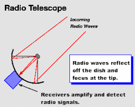
The most familiar type of radio telescope is the radio reflector consisting of a parabolic antenna--the so-called dish or filled-aperture telescope--which operates in the same manner as a television-satellite receiving antenna to focus the incoming radiation onto a small antenna referred to as the feed, a term that originated with antennas used for radar transmissions. In a radio telescope the feed is typically a waveguide horn and transfers the incoming signal to the sensitive radio receiver. Cryogenically cooled solid-state amplifiers with very low internal noise are used to obtain the best possible sensitivity.
In some radio telescopes the parabolic surface is equatorially mounted, with one axis parallel to the rotation axis of the Earth. Equatorial mounts are attractive because they allow the telescope to follow a position in the sky as the Earth rotates by moving the antenna about a single axis parallel to the Earth's axis of rotation. But equitorially mounted radio telescopes are difficult and expensive to build. In most modern radio telescopes a digital computer is used to drive the telescope about the azimuth and elevation axes to follow the motion of a radio source across the sky.
Observing times up to many hours are expended and sophisticated signal-processing techniques are used to detect astronomical radio signals that are as much as one million times weaker than the noise generated in the receiver. Signal-processing and analysis are usually done in a digital computer.
In the simplest form of radio telescope, the receiver is placed directly at the focal point of the parabolic reflector, and the detected signal is carried by cable along the feed support structure to a point near the ground where it can be recorded and analyzed. However, it is difficult in this type of system to access the instrumentation for maintenance and repair, and weight restrictions limit the size and number of individual receivers that can be installed on the telescope. More often, a secondary reflector is placed in front (Cassegrain focus) or behind (Gregorian focus) of the focal point of the paraboloid to focus the radiation to a point near the vertex of the main reflector. Multiple feeds and receivers may be located at the vertex where there is more room, less stringent weight restrictions and where access for maintenance and repair is more straightforward. Secondary focus systems also have the advantage that both the primary and secondary reflecting surfaces may be carefully shaped so as to improve the gain over that of a simple parabolic antenna.
While earlier radio telescopes used a symmetric tripod or quadrarpoid structure to hold the feed or secondary reflector, such an arrangement blocks some of the incoming radiation, and the reflection of signals from the support legs back into the receiver distorted the response. In newer designs, the feed or secondary reflector is placed off axis and does not block the incoming signal. Off axis radio telescopes are thus more sensitive and less affected by terrestrial interference reflected off of the support structure into the feed.
The performance of a radio telescope is limited by various factors: the accuracy of a reflecting surface that may depart from the ideal shape because of manufacturing irregularities; the effect of wind load; thermal deformations that cause differential expansion and contraction; and deflections due to changes in gravitational forces as the antenna is pointed to different parts of the sky. Departures from a perfect parabolic surface become important when they are a few percent or more of the wavelength of operation. Since small structures can be built with greater precision than larger ones, radio telescopes designed for operation at millimeter wavelength are typically only a few tens of meters across, whereas those designed for operation at centimeter wavelengths range up to 100 meters in diameter.
Traditionally, the effect of gravity has been minimized by designing the movable structure to be as stiff as possible in order to reduce the deflections resulting from gravity. A more effective technique, based on the principle of homology, allows the structure to deform under the force of gravity, but the cross section and weight of each member of the movable structure are chosen to cause the gravitational forces to deform the reflecting structure into a new paraboloid with a slightly different focal point. It is then necessary only to move the feed or secondary reflector to maintain optimum performance. Homologous designs have become possible only since the development of computer-aided structural analysis known as finite element analysis.
Radio telescopes are used to measure broad-bandwidth continuum radiation as well as spectroscopic features due to atomic and molecular lines found in the radio spectrum of astronomical objects. In early radio telescopes, spectroscopic observations were made by tuning a receiver across a sufficiently large frequency range to cover the various frequencies of interest. This procedure, however, was extremely time-consuming and greatly restricted observations. Modern radio telescopes observe simultaneously at a large number of frequencies by dividing the signals up into as many as several thousand separate frequency channels that may range over a total bandwidth of tens to hundreds of megahertz.
The most straightforward type of radio spectrometer employs a large number of filters, each tuned to a separate frequency and followed by a separate detector to produce a multichannel, or multifrequency, receiver. Alternatively, a single broad-bandwidth signal may be converted into digital form and analyzed by the mathematical process of autocorrelation and Fourier transformation (see below). In order to detect faint signals, the receiver output is often averaged over periods of up to several hours to reduce the effect of noise generated in the receiver.
Radio Interferometry and Aperture Synthesis
The angular resolution, or ability of a radio telescope to distinguish fine detail in the sky, depends on the wavelength of observations divided by the size of the instrument. Yet, even the largest antennas, when used at their shortest operating wavelength, have an angular resolution only a little better than one arc minute, which is comparable to that of the unaided human eye at optical wavelengths. Because radio telescopes operate at much longer wavelengths than do optical telescopes, radio telescopes must be much larger than optical telescopes to achieve the same angular resolution.
At radio wavelengths, the distortions introduced by the atmosphere are less important than at optical wavelengths, and so the theoretical angular resolution of a radio telescope can in practice be achieved even for the largest dimensions. Also, because radio signals are easy to distribute over large distances without distortion, it is possible to build radio telescopes of essentially unlimited dimensions. In fact, the history of radio astronomy has been one of solving engineering problems to construct radio telescopes of continually increasing angular resolution.
The high angular resolution of radio telescopes is achieved by using the principles of interferometry to synthesize a very large effective aperture from a number of small elements. In a simple two-element radio interferometer, the signals from an unresolved, or "point," source alternately arrive in phase and out of phase as the Earth rotates and causes a change in the difference in path from the radio source to the two elements of the interferometer. This produces interference fringes in a manner similar to that in an optical interferometer. If the radio source has finite angular size, then the difference in path length to the elements of the interferometer varies across the source. The measured interference fringes from each interferometer pair thus depend on the detailed nature of the radio "brightness" distribution in the sky.
Each interferometer pair measures one "Fourier component" of the brightness distribution of the radio source. Work by Australian and British radio astronomers in the 1950s and 1960s showed that movable antenna elements combined with the rotation of the Earth can sample a sufficient number of Fourier components with which to synthesize the effect of a large aperture and thereby reconstruct high-resolution images of the radio sky. The laborious computational task of doing Fourier transforms to obtain images from the interferometer data is accomplished with high-speed computers and the fast Fourier transform (FFT), a mathematical technique that is especially suited for computing discrete Fourier transforms.
In recognition of their contributions to the development of the Fourier synthesis technique, more commonly known as aperture synthesis, or earth-rotation synthesis, Martin Ryle and Antony Hewish were awarded the 1974 Nobel Prize for Physics. During the 1960s the Swedish radio astronomer, Jan Hogbom developed a technique called "CLEAN," which is used to remove the spurious responses from a celestial radio image caused by the use of discrete, rather than continuous, spacings in deriving the radio image. Further developments, based on a technique introduced in the early 1950s by the British scientists Roger Jennison and Francis Graham Smith, led to the concept of self-calibration, which is used to remove errors in a radio image due to uncertainties in the response of individual antennas as well as small errors introduced by the propagation of radio signals through the terrestrial atmosphere. In this way radio telescopes are able to achieve extraordinary angular resolution and image quality, not possible in any other wavelength band.
Very Long Baseline Interferometry (VLBI)
In conventional interferometers and arrays, coaxial-cable, waveguide, or even fiber-optic links are used to distribute a common local oscillator reference signal to each antenna and also to return the received signal from an individual antenna to a central laboratory where it is correlated with the signals from other antennas. In cases in which antennas are spaced more than a few tens of kilometers apart, however, it becomes prohibitively expensive to employ real physical links to distribute the signals. Very high frequency (VHF) or ultrahigh frequency (UHF) radio links can be used, but the need for a large number of repeater stations makes this impractical for spacings greater than a few hundred kilometers.
Interferometer systems of essentially unlimited element separation are formed by using the technique of very long baseline interferometry, or VLBI. In a VLBI system the signals received at each element are recorded by broad-bandwidth videotape recorders located at each element. The recorded tapes are then transported to a common location where they are replayed and the signals combined to form interference fringes. The successful operation of a VLBI system requires that the tape recordings be synchronized within a few millionths of a second and that the local oscillator reference signal be stable to better than one part in a trillion. A single magnetic tape capable of recording for several hours can contain one trillion bits of information, which is roughly equivalent to storing the entire contents of a modest-sized library. Hydrogen maser frequency standards are used to give a timing accuracy of only a few billionths of a second and a frequency stability of one part in a billion billion.

radio telescope


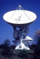
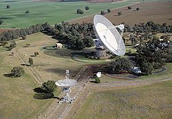
A radio telescope is a form of directional radio antenna used in radio astronomy. The same types of antennas are also used in tracking and collecting data from satellites and space probes. In their astronomical role they differ from optical telescopes in that they operate in the radio frequency portion of the electromagnetic spectrum where they can detect and collect data on radio sources. Radio telescopes are typically large parabolic ("dish") antennas used singly or in an array. Radio observatories are preferentially located far from major centers of population to avoid electromagnetic interference (EMI) fromradio, TV, radar, and other EMI emitting devices. This is similar to the locating of optical telescopes to avoid light pollution, with the difference being that radio observatories are often placed in valleys to further shield them from EMI as opposed to clear air mountain tops for optical observatories.


Early radio telescopes


The first radio antenna used to identify an astronomical radio source was one built byKarl Guthe Jansky, an engineer with Bell Telephone Laboratories, in 1931. Jansky was assigned the job of identifying sources of static that might interfere with radio telephone service. Jansky's antenna was an array of dipoles and reflectors designed to receive short wave radio signals at a frequency of 20.5 MHz (wavelength about 14.6 m). It was mounted on a turntable that allowed it to rotate in any direction, earning it the name "Jansky's merry-go-round". It had a diameter of approximately 100 ft (30 m). and stood 20 ft (6 m). tall. By rotating the antenna on a set of four Ford Model-Ttires, the direction of the received interfering radio source (static) could be pinpointed. A small shed to the side of the antenna housed an analog pen-and-paper recording system. After recording signals from all directions for several months, Jansky eventually categorized them into three types of static: nearby thunderstorms, distant thunderstorms, and a faint steady hiss of unknown origin. Jansky finally determined that the "faint hiss" repeated on a cycle of 23 hours and 56 minutes. This period is the length of an astronomical sidereal day, the time it takes any "fixed" object located on thecelestial sphere to come back to the same location in the sky. Thus Jansky suspected that the hiss originated well beyond the Earth's atmosphere, and by comparing his observations with optical astronomical maps, Jansky concluded that the radiation was coming from the Milky Way Galaxy and was strongest in the direction of the center of the galaxy, in the constellation of Sagittarius.

Reber's first "dish radio telescope - Wheaton, IL 1937
An amateur radio operator, Grote Reber, was one of the pioneers of what became known asradio astronomy when he built the first parabolic "dish" radio telescope (9 m in diameter) in his back yard in Illinois in 1937. He was instrumental in repeating Karl Guthe Jansky's pioneering but somewhat simple work at higher frequencies, and he went on to conduct the first sky survey at VHF radio frequencies. The rapid development of radar technologyduring World War II was easily translated into radio astronomy technology after the war, and the field of radio astronomy began to blossom.


Radio telescope types


The range of frequencies in the electromagnetic spectrum that makes up the radio spectrum is very large. This means that the types of antennas that are used as radio telescopes vary widely in design, size, and configuration. At wavelengths of 30 meters to 3 meters (10 MHz - 100 MHz), they are generally either directional antenna arrays similar to "TV antennas" or large stationary reflectors with moveable focal points. Since the wavelengths being observed with these types of antennas are so long, the "reflector" surfaces can be constructed from coarse wire mesh such as chicken wire.[1] At shorter wavelengths “dish” style radio telescopes predominate. The angular resolution of a dish style antenna is determined by the diameter of the dish expressed as a number of wavelengths of the electromagnetic radiation being observed. This dictates the dish size a radio telescope needs for a useful resolution. Radio telescopes that operate at wavelengths of 3 meters to 30 cm (100 MHz to 1 GHz) are usually well over 100 meters in diameter. Telescopes working at wavelengths above 30 cm (1 GHz) range in size from 3 to 90 meters in diameter.


Big dishes

World's largest single-aperture radio telescope at Arecibo Observatory in Puerto Rico
The world's largest filled-aperture telescope (i.e., a full dish) is the Arecibo radio telescope located in Arecibo, Puerto Rico, whose 305 m (1,001 ft) dish is fixed in the ground. It was designed by engineer Bill Gordon (d. 2010). [2] The suspension system was deigned by George and Helias Doundoulakis, for which Helias Doundoulakis received a patent along with assignee William J. Casey, ex-CIA Director under President Ronald Reagan[1][3]. The antenna beam is steerable (by means of a moving receiver) within about 20° of the zenith. The largest individual radio telescope of any kind is the RATAN-600 located near Nizhny Arkhyz, Russia, which consists of a 576-meter circle of rectangular radio reflectors, each of which can be pointed towards a central conical receiver.
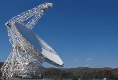
The largest radio telescope in Europe is the 100-meter diameter antenna inEffelsberg, Germany, which also was the world's largest fully-steerable telescope for 30 years until the slightly larger Green Bank Telescope was opened in West Virginia, United States, in 2000. The third-largest fully-steerable radio telescope is the 76-metre Lovell Telescope atJodrell Bank Observatory in Cheshire, England.
A typical size of the single antenna of a radio telescope is 25 meters. Dozens of radio telescopes with comparable sizes are operated in radio observatories all over the world.
China officially started construction of the world's largest single-aperture radio telescope in 2009, the FAST.[4] TheFAST, with a dish area as large as 30 football fields, will stand in a region of typical Karst depressions in Guizhou, and will be finished by 2013.


Radio interferometry


One of the most notable developments came in 1946 with the introduction of the technique called astronomical interferometry. Astronomical radio interferometers usually consist either of arrays of parabolic dishes (e.g. theOne-Mile Telescope), arrays of one-dimensional antennas (e.g. the Molonglo Observatory Synthesis Telescope) or two-dimensional arrays of omni-directionaldipoles (e.g. Tony Hewish's Pulsar Array). All of the telescopes in the array are widely separated and are usually connected together using coaxial cable,waveguide, optical fiber, or other type of transmission line. Recent advances in the stability of electronic oscillators also now permit interferometry to be carried out by independent recording of the signals at the various antennas, and then later correlating the recordings at some central processing facility. This process is known as VLBI (Very Long Baseline Interferometry). Interferometry does increase the total signal collected, but its primary purpose is to vastly increase the resolution through a process called Aperture synthesis. This technique works by superposing (interfering) the signal wavesfrom the different telescopes on the principle that waves that coincide with the same phase will add to each other while two waves that have opposite phases will cancel each other out. This creates a combined telescope that is equivalent in resolution (though not in sensitivity) to a single antenna whose diameter is equal to the spacing of the antennas furthest apart in the array. A high quality image requires a large number of different separations between telescopes. Projected separation between any two telescopes, as seen from the radio source, is called a baseline. For example, the Very Large Array (VLA) near Socorro, New Mexico has 27 telescopes with 351 independent baselines at once, which achieves a resolution of 0.2 arc seconds at 3 cm wavelengths[5]). Martin Ryle's group in Cambridge obtained aNobel Prize for interferometry and aperture synthesis[6]. The Lloyd's mirror interferometer was also developed independently in 1946 by Joseph Pawsey's group at the University of Sydney[7]. In the early 1950s the Cambridge Interferometer mapped the radio sky to produce the famous 2C and 3C surveys of radio sources. The largest existing physically-connected radio telescope array is the Giant Metrewave Radio Telescope, located in Pune, India. A larger array, LOFAR (the 'LOw Frequency ARray') is currently being constructed in western Europe, consisting of 25 000 small antennas over an area several hundreds of kilometres in diameter. VLBI systems using post-observation processing have been constructed with antennas thousands of miles apart. Radio interferometers have also been used to obtain detailed images of the anisotropies and the polarization of the Cosmic Microwave Background, like the CBI interferometer in 2004.

Celestron 21041 60mm PowerSeeker Telescope


Technical Details
Affordable telescope for beginning astronomer; portable yet powerful
All-glass optical components with high transmission coatings for enhanced image brightness and clarity
Refractor optical design with a 60mm aperture and 700mm focal length
Altazimuth mount suitable for terrestial viewing as well as astronomical use
Includes 3x Barlow Lens (1.25"), 20mm eyepiece, 4mm eyepiece, aluminum tripod with accessory tray
Amazon.com Review
Celestron's value priced Powerseeker 60 telescope takes a basic "just the facts" approach to affordable entry level telescopes. The package includes an adjustable aluminum tripod with an alt-azimuth mount and stabilizer, a Kellner type K20 eyepiece, a Ramsden type SR4 eyepiece, a 3x barlow lens, and a 5 power cross-hair finder scope.
The Powerseeker 60 comes disassembled in a compact box, but it won't take long to put everything together. Go ahead and try it out in the daytime, that's the best time to align the finder scope while looking at a distant tree or telephone pole.
My first view of Saturn's rings and star cluster M13 in Hercules came with a 60mm telescope, and I enjoy celestial viewing with the Powerseeker 60 to this day. The secret is to use the low power K20 eyepiece and only extend the tripod legs half-way. This gives me sharp and steady views, whether I'm looking at nearby hills, craters on the Moon, the Double Cluster in Perseus, or even the Andromeda Galaxy!
With a 1.25" focuser and diagonal mirror, it's easy to add better eyepieces. The Kellner type K20 eyepiece yields a 1.1 degree true field of view, better than the Huygens or H-type eyepieces still found in many beginner scopes. Adding an optional Celestron 25mm E-Lux eyepiece is better still. With nearly 2 degrees true field of view, the 25mm E-lux makes it much easier to find objects, either on land or in deep space. The SR4 eyepiece is less impressive; it's like peeking through a pin-hole. Adding the 3x barlow to the SR4 to get that 525x proclaimed on the box is peeking through a dim, fuzzy pin-hole.
I'm surprised that a telescope this inexpensive can be this good. It's good enough to show me Saturn's rings at night or a Steller's Jay at 100 yards during the day. In my opinion, the Powerseeker 60 would be an even better bargain if it came with a K10 eyepiece in place of the 3x barlow and the SR4 eyepiece. Also take a look at Celestron's Firstscope 60AZ; it's only a little more expensive, but it includes two useable eyepieces, a red-dot finder, and planetarium software for your computer. –Jeff Phillips
Pros:
Low cost
Decent optics
Accepts 1.25" eyepieces Cons:
Too small for serious astronomy
Only one good eyepiece
Product Description
The PowerSeekers come with all coated glass optical components with for enhanced image brightness and clarity. The Newtonian reflectors offer larger aperture and greater light gathering power needed to resolve the faint detail of hundreds of deep-sky and other celestial objects. All PowerSeekers come on either sturdy equatorial mounts for tracking the sky, or collapsible altazimuth mounts suitable for terrestrial viewing as well as astronomical use. The PowerSeekers come with a full range of eyepieces plus a 3x Barlow lens, allowing an increase in viewing power hundreds of times greater than that of an unaided eye!

Optical Telescope


Optical telescope is the most common type of telescope available for beginners in astronomy. Optical telescopes are cheaper and have sufficient features to let you view the celestial objects and the electromagnetic radiation in the sky. Other than astronomy they’re also used in theodolite, binoculars, spyglass and camera lenses. As technology progressed optical telescopes are improved a lot giving much better image quality than earlier optical telescopes.
How optical telescope works ?
Optical telescope gathers and focuses the light from the visible portion of electromagnetic spectrum. This allows observer to view image that is being magnified from a longer distance. Optical telescopes have features to adjust the brightness and the size of the image that allows observer to comfortably view the celestial objects easily.
Types of Optical Telescopes
Refracting Telescope
Reflecting Telescope
Catadioptric Telescope
Infrared telescope
Refracting telescope These telescope makes use of a lens that forms the image to let observer view it. As the images with this type of telescope is formed by bending of light or refraction hence they’re called as refracting telescopes. There are many designs of refracting telescopes some of them are : Galileo's telescope, Keplerian Telescope, Achromatic refractor, Apochromatic refractor. Reflecting TelescopeReflecting telescope makes use of single or combination of mirrors to form an image by reflecting the light. These telescope were invented as alternative to refracting telescopes. In comparison to refracting telescopes these telescopes offer bigger and brighter view. So for large scale astronomical research reflecting telescopes are used. Some of the popular designs of reflecting telescope are: Gregorian telescope, Cassegrain telescope, Ritchey-Chrétien telescope, Schiefspiegler telescope.
Catadioptric TelescopeCatadioptric Telescope makes use of both relection and refraction techniques to produce image. They’re usually used in telephoto and microscope instruments.
Infrared telescopesInfrared telescope makes use of an infrared light to form an image. Infrared telescopes require shielding from heat and chilled region in order to form image clear to observer. So it is only used in the region where the environment is suitable for using infrared detector. Other types of optical telescope includes:
Ultraviolet telescope
Fresnel Imager
Submillimetre telescope
Where optical telescopes are used ?
In labs for research (as microscope)
For astronomy research
Telephoto Cameras
Binoculars
Spy glasses
Surveillance Catadioptric Sensors
There are many types of telescopes but optical telescope being affordable, easy to operate becomes first choice for beginner in astronomy. You need to research a little before you purchase optical telescope for your kids or for yourself.

Optical telescope


An optical telescope is a telescope which is used to gather and focus light mainly from the visible part of the electromagnetic spectrum for directly viewing a magnified image for making a photograph, or collecting data through electronic image sensors.
There are three primary types of optical telescope: Refractors (Dioptrics) which use lenses, Reflectors (Catoptrics) which use mirrors, and Combined Lens-Mirror Systems (Catadioptrics) which use lenses and mirrors in combination; for example, the Maksutov telescope and the Schmidt camera.
A telescope's light gathering power is directly related to the diameter (or aperture) of the objective lens or mirror. The larger the lens is, the more light the telescope can collect. What is commonly described as a telescope's power, its magnification, is a function of both the objective's focal length and that of the eyepiece.

Telescope

A telescope is an instrument designed to aid the observation of remote objects by collecting some form of electromagnetic radiation (such as visible light). The first known practical telescopes were invented in the Netherlands at the beginning of the 17th century. The word telescope can refer to a wide range of instruments detecting different regions of the electromagnetic spectrum.